Overlays and underlays networks in SDN
The phenomenon that can be observed nowadays is the exponential growth of the internet. Certainly there can be not a shred of a doubt here just a month ago as the IPv4 addresses ran out, all IT companies considered migrating to a cloud, so the distributed storage and computing power can be bought everywhere. As a result, growth data centers must deal with huge amounts of servers, networks, fibers, routers and all other elements from L1-L3 that you could possibly image. Network administration became quite a different thing from what it used to be barely a few years ago. For data centers and large industries, Software Defined Networking can be a clear approach to dealing with scalability and availability of a network. SDN stirs up a lot of discussions among engineers, developers and administrators; and concerns each of the OSI layer. In the Software industry, each protocol and technology can only either evolve or die out. Of course studying old and deprecated protocols can be quite instructive and valuable, especially for scientists who create protocols. Yet in this post we shall focus on overlay networking and discuss their use cases, architecture, and low-level details how it works.
Multi-tenancy, VLAN-s, networks isolation and other requirements for DC (Data Centers).
Each Data Center that provide to customers hosting or infrastructure must face the same set of problems: they need virtualization, network scalability, high availability and few more things like scalability and flexibility. Let’s consider the case when a customer needs its own private network with database and application server. To meet this requirement a separate physical network can be created, with a separate node to an application server and database. But this approach can be rather difficult and, more importantly, it may be a killer from the economical point of view. Moreover, we also have great tools to virtualization such as KVM, XEN, vSphere. Thus we are able to run thousand of VMs on a single physical server, and each one of those thousand clients needs to be in a separate network. The network isolation is a fundamental thing when we provide hosting services. Also, in the data center we can rely on a physical position of server or port. This is so because quite often it may be necessary to migrate one VM to another machine because of client demand or even because of a physical damage of bare metal, disk or anything else. The ideal solution would be that of totally separating the DC network architecture to made it independent from services and VMs, VPNs. To solve this problem was introduce a separation between underlying and overlaying networks.
Overlay and underlay.
The overlay networks are built on top of the underlay networks. But what exactly does it mean? Let’s think about it in this way: we want to be independent of our physical network, but we have to consider it. Let’s made some abstraction and encapsulate our network (create a network on top of the existing network). Through encapsulation, we get 2 networks: an overlay network when can be placed clients infrastructure isolated and separate between tenants, and an underlay network when DC can hold and consider L2-L3 devices.
The main overlaying network technologies are: -VXLAN -MPLS-over-UDP -MPLS-over-GRE
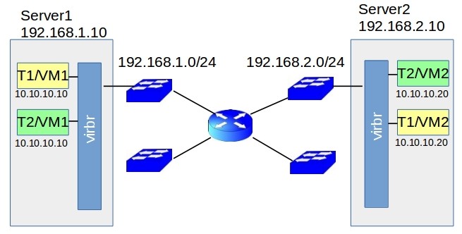
Let’s consider the following case: In our Data Center, we have 2 servers: Server1 and Server2 that are separated by L3 barrier router. On each server, 2 VMs was spawned from two different tenants (consider tenant1 need more calculation power and tenant 2 has lightweight VM so that can be why we had 2 VM from one tenant on 2 different bare metals). This case is illustrated in the #1 picture.

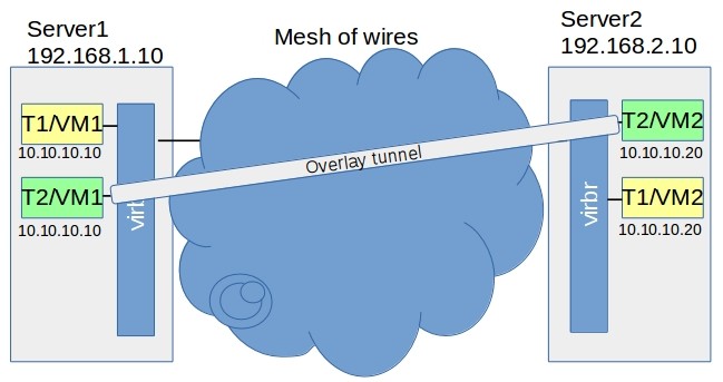
As we can see it is not possible to reach VM1 Tenant1 to VM2 using standard networking. Moreover, Tenant2 is also unable to do it, and it also has similar inter numeration in its network. It may be hard to create 2 different separate isolated networks for these tenants by means of standard networking configuration for a underlaying network because it should be dependent on overlaying networks and this is a thing that we really did not want and now trying to omit. But let’s get back to our main topic we started with underlying networks and overlaying networks. So, in this case, we considering the underlying network, because we are dealing with lower layers of OSI model, and also with physical devices. Now nets thing in that way, what do we want to receive by abstraction in this case? It would be great to have something like a virtual tunnel between VM1 and VM2 to have a direct connection between VMs. So we want to have a connection between VM’s per tenant and not need to worry about underlay networks.That can be illustrated in the #2 picture.

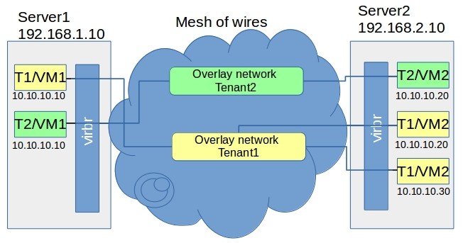
The tunnel can be easily associated with a p2p connection, but in our case we need scalability in order to deal with several VMs or VPNs. To illustrate this point, let’s also add another VM to tenant2 (because it could be in example more lightweight). Now we can see that it can’t be a just a tunnel, it have to be a full network. So let’s create 2 networks, each separate per tenant. What we get in this case is presented in the scheme below, and definitely it is something that fulfill our requirements. This approach is illustrated in the #3 picture.

Ok, that seems quite awesome but let’s proceed to elaborate it in more detailed way. Namely, the problem we are about to face now is: how can we implement that kind of network isolation in the real world?!
Having learned what overlay and underlay networks are, we also briefly discussed our needs already. Now is the time to see how that encapsulation and separation actually work in the real world. To get a good understanding of how things work sometimes, it helps to get back to the basics. Thus, let’s start from, admittedly rather boring, ethernet packet structure:
An Ethernet frame is preceded by a preamble and start frame delimiter (SFD),
both of which from parts of the Ethernet packet at the physical layer.
Each Ethernet frame starts with an Ethernet header, which contains destination
and source MAC addresses as these are the first two fields. The middle section
of the frame is payload data including any headers for other protocols (for example,
Internet Protocol) carried in the frame. The frame ends with a frame check sequence (FCS),
which is a 32-bit cyclic redundancy check used to detect any in-transit corruption of data.
For our needs, we can switch Layer 1 header (Preamble and SFD) and switch into layer two. In L2 we have: -Destination and Source MAC addresses -Optional VLAN -Ethernet Type -Payload that sometimes is referred to as L3-L7 frame -FCS: Frame Check Sequence

The idea of an overlaying network is to create the second frame that will belong to underlay network, and as a payload put an overlay network frame. Here the underlay network can operate without considering the overlay network, so what we receive in a result is the desired isolation and encapsulation.
VXLAN:
As the most popular overlay solution, I will describe the VXLAN structure. One thing that we already know is that inside this frame an L2 frame has to be nested. As you can see in the a diagram, in VXLAN we had an outer packet and an inner original L2 frame. VXLAN is a protocol that embedded L2 frame into L3, so in result we have L3 Outer frame.

Inside the Outer frame we had: Outer MAC Header (so again like in the Eth frame):
- Dst Address MAC
- Source Address MAC
- VLAN TAG
- ETH type
Next the outer IP Header (we are in L3) that contains 20 Bytes:
- IP Header (version, length TOS, total length)
- Identification: 2 bytes
- Flags and offset: 2 bytes
- ttl: 1 byte
- Protocol: 1 byte
- Header checksum: 2 bytes
- Source Address: 4 bytes
- Destination address: 4 bytes
Outer UDP Header 8 Bytes:
- Source Port: 2 bytes
- Destination port: 2 bytes (here we store VXLAN port because we are dealing with it)
- UDP length: 2 bytes
- Checksum: 2 bytes
And the last fragment of underlay frame 8 Bytes
- VXLAN Flags: 1 byte
- Reserved: 3 bytes
- VXLAN Segment ID/VXLAN Network Identifier (VNI) : 3 bytes (24 bits)
- Reserved 1 byte: [Reserved fields (24 bits and 8 bits): MUST be set to zero on transmission and ignored on receipt]